
Instead of using x and y this system uses the following coordinates:

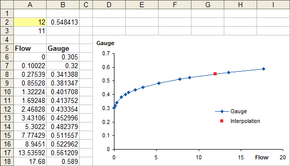
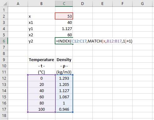
The common reference system of choice are the Lagrangian surface coordinates. b) The Lagrangian coordinate system uses the areas of the subtriangles created by the point S. a) The dependent function g is approximated with g ˜ within the triangle. Lagrangian coordinate system used as a local coordinate system within a single triangle of an FEM mesh. If it is not a good representation of the material behavior, you should increase the number of material property data points until it is. You should check the approximation before issuing the SOLVE command. However, if an insufficient number of data points are supplied, the material property values used by the program may not adequately reflect the behavior of the real material.įortunately, the program also graphs temperature-dependent material properties and material property data using a linear interpolation between data points, so you can visualize your material data curves when they are defined. As the number of data points increases, this technique approximates a smooth curve. Thompson PhD, PE, in ANSYS Mechanical APDL for Finite Element Analysis, 2017 5.6.3 Insufficient Number of Points on a Material Data CurveĪNSYS uses linear interpolation to evaluate all data stored in tables, including material data curves. Therefore, to accurately monitor the OSNR in reconfigurable transparent optical networks, it is necessary to measure the in-band ASE noises under the channel's wavelength. Based on this optical spectrum, the linear interpolation techniques may determine that all channels have the same OSNR. However, it is impossible to identify this difference from the spectrum in Figure 2.6(a), which was obtained with the 43-Gb/s RZ-DQPSK signals. Thus, the channels in this group have worse OSNR values than those in the other, as clearly seen in Figure 2.6(b), which was obtained when the CW signals were transmitted. One group of channels (i.e., the four channels located on the left side) was transmitted over a longer route than the other. Figure 2.6 compares the spectrum of 43-Gb/s return-to-zero (RZ) differential quadrature phase-shift keying (DQPSK) signals with that of CW signals the spectrum was measured after turning off the modulators. The spectral power of the phase-modulated signals tends to be well distributed like ASE noises since they often have no carrier component carrying strong optical power. The situation is exacerbated when high-speed phase-modulated signals are transmitted with dense channel spacing. Thus, in such a case, linear interpolation techniques could induce a large error in OSNR measurement. In addition, it is not easy to identify the levels of the filtered ASE noises if the channels are modulated at a high bit rate, as shown in Figure 2.5(c). Since the ASE noises between channels are significantly filtered out at every node, the levels of the ASE noises under the channel wavelengths have no correlation with those between the channels.

The spectrum of the ASE noises is significantly reshaped due to optical filtering at each ADM node. Figure 2.5(b) shows the optical spectrum obtained at point A when unmodulated continuous-wave (CW) signals are transmitted. Thus, the wavelength channels have different OSNR levels when they are observed at point A of the link. In this scenario, each wavelength channel should traverse a different number of ADM nodes. The other wavelength channels pass through the node transparently in the optical layer. At each ADM node, a certain wavelength channel is dropped and a new channel having an identical wavelength is added. Eight wavelength channels are multiplexed and transmitted over seven add/drop multiplexing (ADM) nodes. 11 Figure 2.5(a) shows an example of such a case in an optical network consisting of ROADMs. However, in dynamically reconfigurable networks, the accuracy of these techniques could be severely degraded because the spectrum of the ASE noises could have irregular levels that vary with the wavelength. Linear interpolation techniques are very useful for measuring the OSNR of WDM signals in point-to-point optical links.


 0 kommentar(er)
